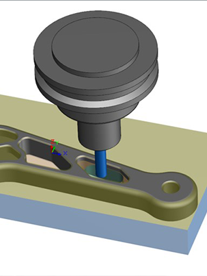


It is a parametric 3D design software that enables engineers to create and work with 3D models, with a user-friendly interface. Software SolidWorks free download is a computer-aided design (CAD) and computer-aided engineering (CAE) application that is used in the manufacturing industry.

It is often used in the automotive, aerospace, and product design industries. It is a very powerful and user-friendly CAD software that has a wide range of features and can be used in a number of industries. Product SolidWorks download is a computer-aided design software used for 3D modeling, wire-frame modeling. The app is available for Mac and Windows platforms, and users can purchase the software for $3,000. Application offers an interactive, user-friendly interface with many features for designing, modeling, and drawing. The origin is now set precisely on the coordinate system that was created.SolidWorks is a CAD (Computer-Aided Design) software package for 3D modeling, 3D printing, 2D drafting.

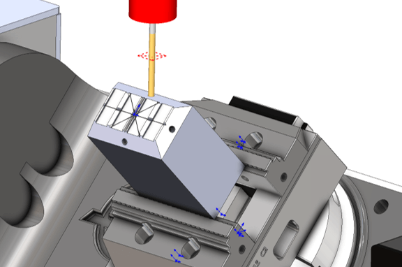
In the Origin tab, select Fixture coordinate system so that the origin will update to the coordinate system. You will then need to Edit Definition for the Mill Part Setup in the CAMWorks Operation tab. Then select the Setup tab and you will need to select the Coordinate System so that it populates in the Selected entity box. Once in CAMWorks, right-click on CAMWorks NC Manager and select Define Machine. When finished you will have a Coordinate System in the FeatureManager Tree and it will be displayed on the part. To do this, we will select the point where the construction lines meet, then select one of the construction lines to be our “X” axis and the other the “Y” axis with the “Z” axis then becoming able to toggle up or down. Then the X, Y, and Z axis need to be defined as well as a point. It’s found in the Reference Geometry drop-down. Now the Coordinate System feature needs to be selected. In this example, I have created a sketch that has two construction lines 90 degrees from each other which will be my X and Y axis. Creating a Coordinate System in CAMWorks can help orient your part and is necessary when programming a 4th or 5th axis part and assemblies.īelow is the part that will be used in this demonstration.Īn origin can be created without using a sketch to define it, however, using a sketch is a preferred method especially when the part doesn’t have 90-degree angles.


 0 kommentar(er)
